
The FAQ/HOW-TO that is out there currently is located at http://mario.germain.com/abs.html [now its here] and is geared towards the T/E/L. I own a 1992 Mitsubishi Galant VR4 and purchased the PocketLogger and the current how-to excludes my little segment of the DSM Community. I have performed this mod to my VR4 and works beautifully but prudence dictates that I should warn you to do this mod at your own risk.
Let's begin! First print out the following:
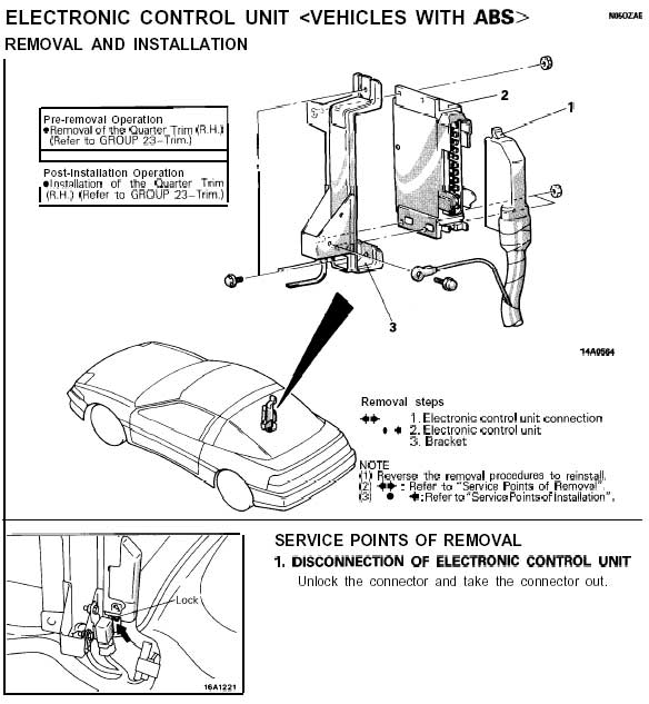
(1) T/E/L Electronic Control Unit Location
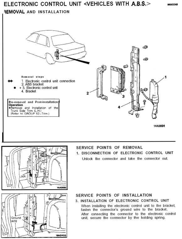
(2) VR4 Electronic Control Unit Location
(3) ABS Electronic Control Unit Circuit Diagram
The above files, along with Mario Germain's FAQ were the only files that I used to figure out a universal/better way of implementing this mod.
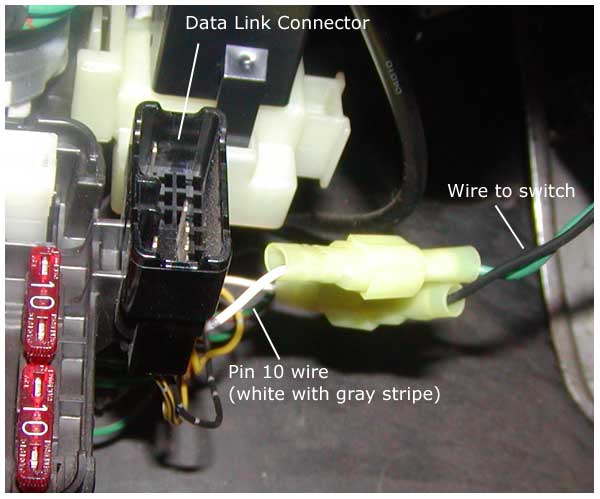
By looking at the circuit diagram, you can see that pin 24 from the ABS Electronic Control Unit goes to pin 10 of the Data Link Connector. I compared this with the T/E/L circuit diagram to find the "pink" wire that is referred to at http://mario.germain.com/abs.html. The "pink" wire, pin 24 on the ABS Electronic Control Unit that goes to pin 10 of the Data Link Connector, is white with gray stripes in the Galant VR4. I asked the question, why not tap from pin 10 on the Data Link Connector instead? Wouldn't that make it easier to put a switch near the driver since it is already under the dash? Well, it turns out that it works using pin 10 wire. Here's a blow up image of the Date Link Connector for reference in finding pin 10:
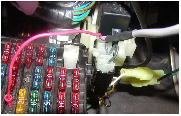
Here are some pictures of my ABS switch installation:
Where to tap for the switch
With the PocketLogger cabled plugged in
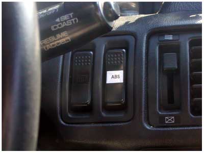
The switch was scavenged from the junkyard, it's an old fog light switch.
Written: 5/28/2002
Author: Hywell Martinez